Gold Recovery Activated Carbon: Complete Guide for Gold Mining Operations
From Carbon Selection to Circuit Optimization—Everything a Gold Mine Operator Needs to Know
Date: July 23rd, 2026
Author: Yicarb Technical Expert (15+ years experience in activated carbon industry)
Note: The examples presented in this article are illustrative scenarios based on common challenges in gold recovery operations. They are intended to demonstrate technical considerations and potential outcomes under specific operating conditions. Actual performance may vary depending on ore characteristics, process parameters and operational factors.
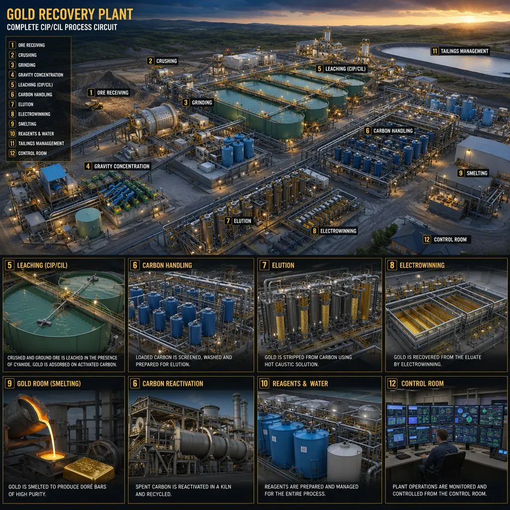
Figure 1: Complete gold recovery plant with CIP/CIL carbon adsorption circuit, elution columns, and gold room.
Abstract: Activated carbon is the backbone of modern gold hydrometallurgy, serving as the primary adsorption medium in CIP (Carbon-in-Pulp), CIL (Carbon-in-Leach), and CIC (Carbon-in-Column) circuits worldwide. This comprehensive guide covers every critical aspect of gold recovery carbon—from understanding process types and key specifications to selecting the right carbon for your ore body, troubleshooting common circuit problems, and evaluating total cost of ownership. Two detailed case studies from Canada and Australia demonstrate how the right carbon selection and circuit management deliver measurable improvements in recovery, operating cost, and plant availability.
1. Understanding Gold Recovery Processes: CIP, CIL, and CIC
The first step in selecting the right activated carbon is understanding which adsorption process your plant operates. Each process places different demands on the carbon:
1.1 Carbon-in-Pulp (CIP)
In CIP, leaching and adsorption occur in separate circuits. The ore is fully leached with cyanide in dedicated tanks before the pulp is transferred to a series of carbon adsorption tanks. Since the gold-cyanide complex [Au(CN)₂]⁻ is already fully dissolved and stable, the carbon’s primary requirement is high loading capacity (K-Value). Carbon advances counter-currently through 5–8 stages, with loaded carbon typically containing 3,000–8,000 g Au/tonne before elution. CIP is best suited for ores without preg-robbing characteristics.
1.2 Carbon-in-Leach (CIL)
CIL combines leaching and adsorption in the same tanks, reducing capital costs by eliminating separate leach vessels. However, this integration creates a more demanding environment: the carbon must compete with the ore for freshly dissolved gold. In ores containing natural carbonaceous matter (preg-robbing), this competition is especially fierce. CIL carbon must prioritize fast adsorption kinetics (R-Value) above all other specifications—gold must be captured the moment it dissolves, before the ore’s native carbon can sequester it irreversibly.
1.3 Carbon-in-Column (CIC)
CIC is used for heap leach and vat leach operations where pregnant solution is pumped through fixed-bed carbon columns rather than mixed with pulp. The absence of slurry means mechanical attrition is minimal, so hardness requirements are less stringent. However, CIC carbon must have excellent hydraulic permeability and resistance to fouling from precipitated salts and colloidal material. Particle size is typically larger (6×12 mesh) to minimize pressure drop across the column.
2. Key Carbon Specifications and How to Interpret Them
Activated carbon for gold recovery is characterized by several standardized metrics. Understanding what each number means—and how it translates to plant performance—is essential for informed carbon selection:
|
Specification |
Standard |
Test Method |
What It Means for Your Operation |
|
Iodine Number |
900–1200 mg/g |
ASTM D4607 |
Total micropore volume. Higher = more surface area for gold adsorption. Coconut carbon typically achieves 1050–1200 mg/g; coal-based 900–1000 mg/g. |
|
R-Value (Kinetics) |
55–75% |
AARL method |
Adsorption rate in 30 min. Critical for CIL circuits with short residence times. > 65% recommended for preg-robbing ores. |
|
K-Value (Loading) |
25–35 mg Au/g |
Freundlich isotherm |
Equilibrium loading at 1.0 mg/L Au. Critical for CIP circuits where carbon contact time is abundant. Directly impacts carbon inventory size. |
|
ASTM Hardness |
97–99.5% |
ASTM D3802 |
Mechanical attrition resistance. Every 1% drop below 98.5% can increase gold-in-fines losses by 15–20%. Non-negotiable for agitated tanks. |
|
Particle Size |
6×12, 6×16, 8×16 mesh |
Sieve analysis |
Uniformity is more important than absolute size. PSD > 95% on-spec prevents screen blinding. Finer mesh = faster kinetics but higher pressure drop. |
|
Ash Content |
< 2–3% |
ASTM D2866 |
Lower ash = less metal leaching into process water. Coconut shell carbon naturally achieves < 2.5%. Coal-based typically 4–10%. |
|
Apparent Density |
0.45–0.55 g/mL |
ASTM D2854 |
Reflects carbon packing and structural integrity. Consistent density ensures predictable carbon inventory weight in each tank. |
3. Carbon Selection Decision Framework
Use the following decision tree to guide carbon selection based on your specific operating conditions:
• Step 1—Identify Circuit Type: CIL → prioritize R-Value. CIP → prioritize K-Value. CIC → prioritize particle size uniformity and low pressure drop.
• Step 2—Characterize the Ore: Test for preg-robbing potential (graphitic carbon, organic shale). If preg-robbing index > 20%, R-Value becomes the dominant specification regardless of circuit type.
• Step 3—Evaluate Agitation Intensity: High-shear, high-power-number impellers (common in large tanks) demand ASTM Hardness > 99%. Lower-shear air-lift systems can tolerate 97–98%.
• Step 4—Assess Carbon Handling System: Pneumatic transfer creates more attrition than eductors or recessed-impeller pumps. Factor transfer method into hardness requirements.
• Step 5—Select Precursor: Coconut shell → highest hardness, lowest ash, best for CIL and high-attrition circuits. Coal-based → larger mesopore volume, cost-effective for CIP with moderate conditions.
• Step 6—Calculate Total Cost of Ownership: Do not evaluate carbon on purchase price alone. Factor in make-up rate, gold-in-fines losses, screen maintenance downtime, and regeneration cycles.
4. Operational Best Practices for Carbon Management
Even the best carbon will underperform if not managed correctly. The following practices are recommended for all CIP/CIL/CIC operations:
• Pre-Attrition: Always pre-attrit fresh carbon with water in an agitated tank for 2–4 hours to remove weak grains and sharp edges before introducing it to the circuit. This prevents the initial surge of fines that follows every carbon change-out.
• Carbon Concentration Monitoring: Maintain 15–25 g/L carbon concentration in each adsorption tank. Lower concentrations reduce gold loading kinetics; higher concentrations increase inter-stage screen loading and attrition.
• Screen Integrity: Inspect inter-stage screens daily for wear, blinding, and mechanical damage. A single failed screen can short-circuit the entire carbon advancement profile.
• Carbon Advance Rate: Advance carbon at 10–25 g carbon per tonne of ore processed. Monitor barren solution gold tenor daily—an upward trend indicates insufficient carbon transfer or declining carbon activity.
• Elution and Regeneration: Strip carbon at 2–3 bed volumes of eluant at 110–120°C. After elution, thermally regenerate at 650–750°C in a rotary or fluidized-bed kiln. Regenerated carbon should recover > 95% of virgin iodine number.
5. Case Studies: Complete Circuit Transformations
Case 5.1: Full Carbon Management Overhaul in a CIP Plant (British Columbia, Canada)
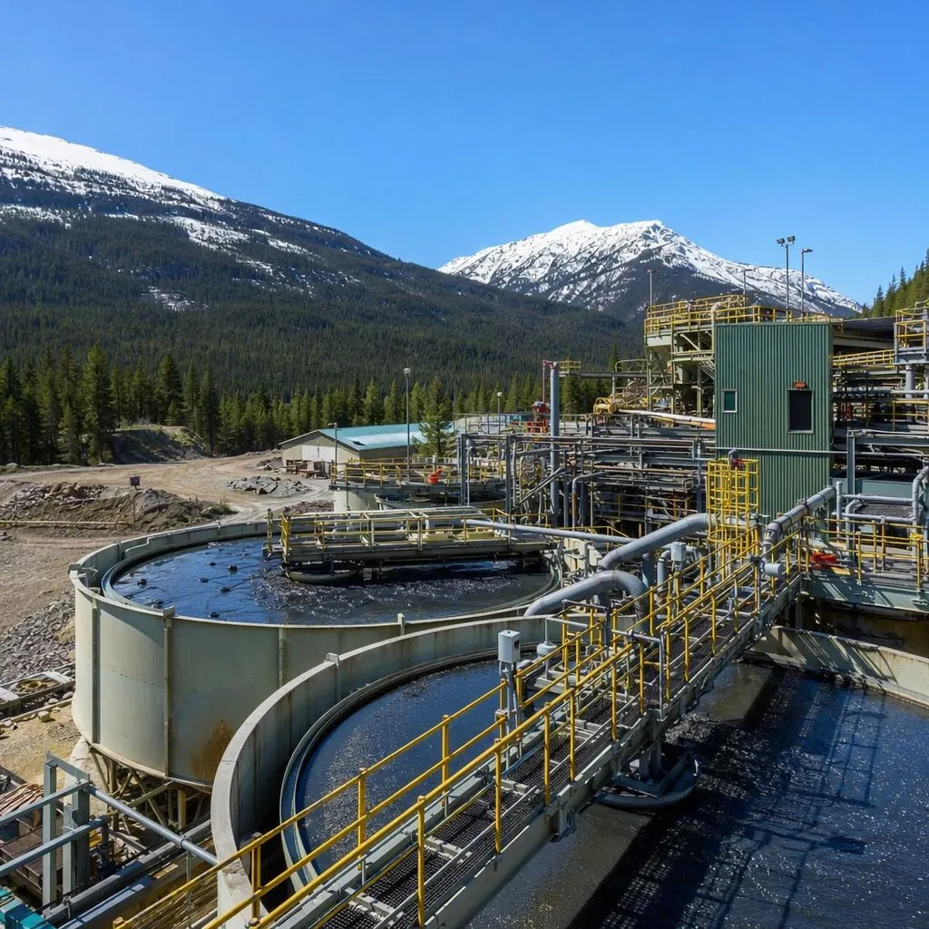
Figure 2: CIP gold processing plant in British Columbia, Canada, with optimized carbon management.
Operational Challenge: A 150,000 oz/year CIP operation in British Columbia’s Golden Triangle was processing a complex sulfide ore with preg-robbing potential of 18%. The plant had been operating for five years using a coal-based carbon selected by the original EPC contractor, achieving average recovery of 93.2%. Over the preceding 18 months, recovery had slowly declined to 91.8%, and carbon make-up had increased from 35 to 52 g/t ore. The plant metallurgist identified multiple contributing factors: carbon fines escaping inter-stage screens, declining carbon activity after regeneration, and inadequate pre-attrition of fresh carbon. Annual gold-in-fines losses were estimated at 1,450 ounces.
The YICARB Solution: We conducted a three-week on-site audit covering carbon sampling, screen inspection, elution/regeneration parameters, and gold mass balance. The audit identified five corrective actions: (1) replace the coal-based carbon with YICARB KinetiGold Coconut Carbon (6×12 mesh, R-Value 71%, ASTM Hardness 99.2%, Iodine 1120 mg/g) to address both kinetics and attrition; (2) install a dedicated pre-attrition tank with 3-hour contact time before fresh carbon enters the circuit; (3) recalibrate the regeneration kiln from 620°C to 700°C with controlled steam injection to restore micropore volume; (4) replace worn inter-stage screen panels (0.8 mm aperture) on stages 3 and 5; and (5) implement daily barren solution gold monitoring with a control chart trigger for carbon advance rate adjustment.
Results: Plant recovery increased from 91.8% to 97.1% within 60 days—an improvement of 5.3 percentage points, representing approximately 7,950 additional ounces of gold per year at unchanged mill throughput. Carbon make-up rate dropped from 52 to 30 g/t ore (42% reduction). Fines-related gold losses fell by 83%. Regenerated carbon iodine number improved from 780 to 1040 mg/g (93% of virgin). The capital investment of USD 185,000 (pre-attrition tank, screen replacements, kiln recalibration) achieved payback in under six weeks. The mine’s Chief Metallurgist commented: “This wasn’t just a carbon swap—it was a complete circuit optimization. Every single performance metric improved.”
Case 5.2: From Coal to Coconut—CIL Circuit Carbon Transformation (Western Australia)
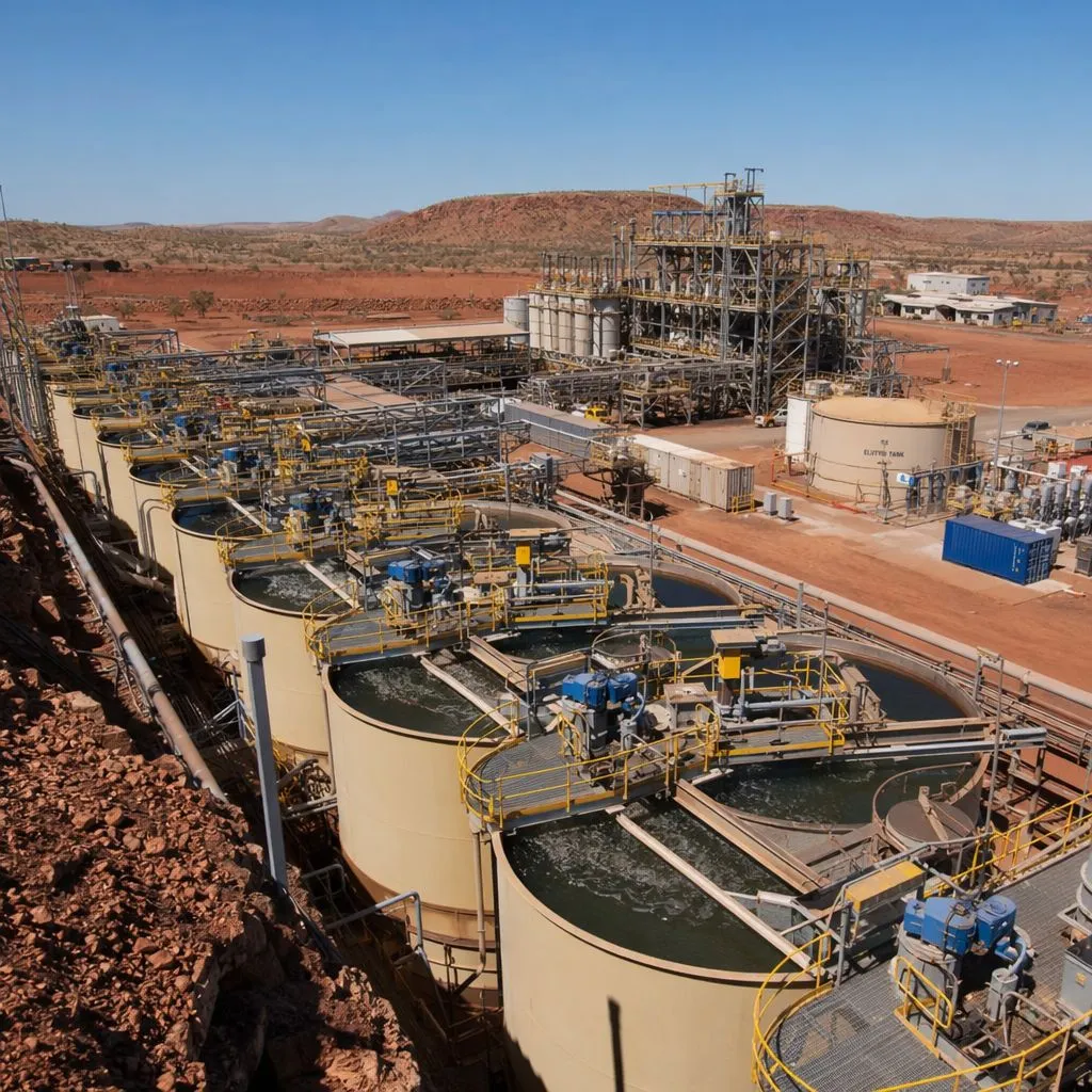
Figure 3: CIL gold processing plant in Western Australia after transitioning from coal-based to coconut shell carbon.
Operational Challenge: A mid-tier gold producer in Western Australia’s Eastern Goldfields, operating a 900,000 tonnes/year CIL circuit with 8×12 mesh coal-based carbon, was experiencing chronic operational issues. The carbon’s ASTM hardness of 96.8% was causing excessive fines generation, with daily make-up rates of 58 g/t—nearly double the design specification of 30 g/t. High ash content (7.2%) was leaching calcium and iron into the process water, accelerating scale formation in the elution heat exchangers and requiring acid cleaning every 18 days. Additionally, the carbon’s R-Value of 51% was inadequate for the ore’s 12% preg-robbing index, resulting in soluble gold losses of 0.09 g/t in tailings.
The YICARB Solution: We implemented a phased transition to YICARB EcoGold Coconut Carbon (8×16 mesh, R-Value 70%, K-Value 29 mg Au/g, ASTM Hardness 99.3%, Iodine 1150 mg/g, Ash < 2.0%). Phase 1 replaced 40% of the carbon inventory over two weeks to allow operators to observe the performance difference. Phase 2 completed the full transition over the following four weeks. The finer 8×16 mesh was selected to increase the external surface area-to-volume ratio, providing faster initial adsorption kinetics—critical for the preg-robbing environment—while the higher hardness was expected to offset the increased surface area’s vulnerability to attrition.
Results: After full transition, the operation achieved: (1) Gold recovery improved from 92.1% to 96.4%, driven by the higher R-Value carbon capturing gold before preg-robbing could occur—soluble tailings gold dropped to 0.03 g/t; (2) Carbon make-up fell to 27 g/t ore (53% reduction), saving USD 93,000/year in procurement; (3) Elution heat exchanger cleaning intervals extended from 18 days to over 90 days, saving 28 days of annual downtime; (4) Gold-in-fines losses decreased by 78% due to the 2.5-percentage-point improvement in ASTM hardness. Total annual benefit exceeded USD 620,000 against a carbon cost increase of only USD 38,000. The operation standardized on YICARB coconut carbon across its entire Australian portfolio.
6. Frequently Asked Questions
Q: How often should carbon be thermally regenerated?
After elution, carbon should be thermally regenerated after every 5–10 loading cycles, depending on the rate of fouling from organic matter, calcium carbonate, and silicates. Monitor regenerated carbon iodine number—if it falls below 85% of virgin specification, increase regeneration frequency or temperature.
Q: What is the typical carbon inventory in a CIP/CIL plant?
Carbon inventory is typically 15–25 tonnes per 100,000 tonnes of annual ore throughput. The exact figure depends on the number of adsorption stages, carbon concentration per tank, and the K-Value of the carbon. Higher K-Value carbon can reduce inventory by 20–25% for the same gold loading target.
Q: Can coconut shell and coal-based carbon be mixed in the same circuit?
Yes, during a transition period. The two carbon types are chemically compatible and can mix without adverse reactions. However, due to density and particle shape differences, they may segregate in transfer lines and tanks. For consistent performance, complete the full transition within 4–6 weeks. Conduct sampling before, during, and after the transition to quantify the performance improvement.
Q: How do I calculate the payback period for switching to a premium carbon?
The payback formula includes four components: (1) carbon cost difference (higher price per tonne × annual consumption), (2) gold recovery improvement (additional ounces × gold price), (3) carbon make-up reduction (lower g/t consumption × carbon price), and (4) downtime savings (fewer screen cleaning events × lost production hours × hourly gold output value). In most cases, even a 20–30% carbon price premium pays back within 3–8 weeks from the gold recovery improvement alone.
7. Conclusion: Carbon Is a Strategic Asset, Not a Commodity Purchase
Activated carbon represents only 2–5% of a gold mine’s total processing costs, yet it directly determines the single most important performance metric: gold recovery. The difference between a commodity-grade carbon purchased on price alone and an engineered carbon matched to the ore body and circuit design can represent 3–8 percentage points of recovery—translating to millions of dollars annually for a typical mid-tier operation.
The complete guide above covers the entire carbon lifecycle: process selection (CIP/CIL/CIC), specification interpretation, decision framework, operational best practices, and total cost of ownership analysis. The two case studies from Canada and Australia demonstrate that systematic carbon optimization—not simply carbon replacement—consistently delivers recovery improvements of 4–5 percentage points and annual savings in the hundreds of thousands of dollars.
YICARB partners with gold mining operations at every stage—from laboratory-scale carbon selection testing to full-scale circuit audits and ongoing technical support. Our application-engineered coconut shell and coal-based carbons are backed by documented performance data and a commitment to measurable results.

Products
Solutions
Performance
Markets & Cases
Resources
Manufacturing & Quality
About Us
Contact Us

Copyright © 2026 Guangdong Yicarb Activated Carbon Co., Ltd. All Rights Reserved.